Official distributor of

Europe GmbH for ferrites in Europe

RM
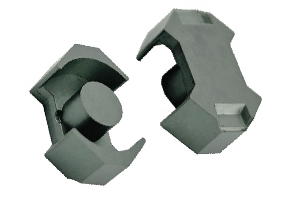
 The demand for coil formers with integrated pins for efficient winding gave rise to the development of compact RM (Rectangular Modular) cores. Furthermore, this design allows high PCB packing densities. RM coil formers and accessories are suited to automatic processing. TDK (Epcos) offers 8 standard sizes (RM 4 through RM 14) of RM-configured cores with standard height and low height (low profile).
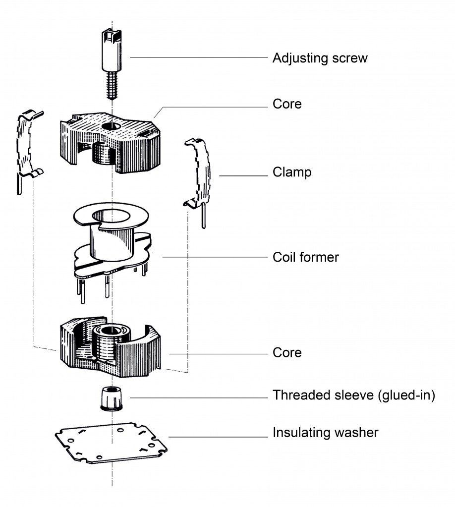
 During assembly, RM cores are held in place by clamps which engage in recesses in the core base. The various clamping forces defined, which have been verified by EPCOS through measurements, are specified in the individual data sheets.
The core dimensions are matched to standard PCB grids. RM 6 means, for example, that the core with coil former fills a square basic area 6 × 6 modules (1 module 2.54 mm) = 15.24 × 15.24 mm2.
Applications:
• Originally RM cores from Siemens (today EPCOS) were essentially designed for two major applications, i.e.
– very low-loss, highly stable filter inductors and other resonance determining inductors (materials N48, M33 and K1) and
– low-distortion broadband transmission at low signal modulation (materials T66, T38, T57, N30).
Even today there is still a high demand for RM cores suited to these applications.
• RM cores are increasingly required for power applications. For this purpose core series made of materials N87, N97, N88, N96, N95, N92, N49 and PC200 (ungapped) is particularly well suited. Matching coil formers with larger pin spacings are available. RM cores without center hole (higher AL value and greater power capacity) are used for transformer applications.
• Product range also includes low-profile RM cores, whose significantly reduced overall height makes them suitable for small-signal, interface and matching transformers and also for transformer and energy storage chokes in DC/DC converters with a high pulse rate (materials N87, N49 and PC200). The low-profile types are particularly suited for applications where the winding is printed onto the PCB and the core is fitted to the board from either side.
• In addition to conventional accessories, SMD coil formers are available for RM 4 LP, RM 5 and RM 6.
• For power applications, particularly for compact energy storage chokes, Epcos supply the RM 12 and RM 14 cores with optimized, strengthened base thickness.
RM-cores Dimensions

Coil formers for automatic processing
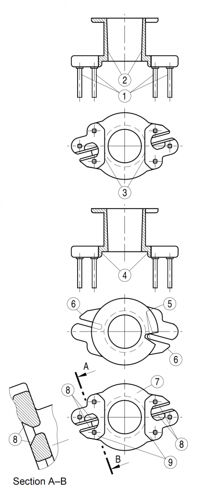
Automated manufacture is gaining more and more importance for the low-cost production of inductive components. The prerequisites are high-performance winding and assembly machines on the one hand, and suitable accessories on the other.The new EPCOS RM coil formers were developed to meet this demand. These coil formers are not only matched to the versatile concepts of automation, but also offer advantages for manual winding. The essential improvements of the version optimized for automatic processing will be described in the following, taking the example of an RM6 coil former. The consistent utilization of these benefits will in most cases bring about a reduction of production costs for inductors and transformers.

➀ Squared pins or pin squared in the start-ofwinding area: Secure restraint of the ends of the winding even with 2 to 3 winding corners; the winding process is considerably accelerated.
➁ Internal diameter slightly conical and highly accurate: Easy and fast slipping-on and snug fit on the winding tools.
➂ Shortened wire guidance slots: Substantially higher flange breaking strength.
➃ Almost parallel flanges with minimum radii at the winding cylinder to the flange: Correct winding layers, more turns, neat and rapid winding.
➄ V-shaped slot in the pinless flange: Automatic loading and unloading of winding machine possible. Substantially more accurate fixing and arrangement of the coil formers.
➅ Lengthened wire catching nose: Leads all wires safely into the wire guidance slots, even at high winding speed.
➆ Pinless flange without marking: Substantially more accurate arrangement of the coil formers for winding and wrapping.
➇ Slot outlet stepped in height: Owing to the transfer of the wire crossing to the level of the slot, short circuit is prevented when soldering the ends of the winding to the pins.
➈ Insulation web: Improved insulation between the winding wires Section A–B and the ferrite core.
Example of Assembling a Set on RM Ferrite Cores

Low Height Profile Ferrite Cores
To obtain low height profile transformers and chokes based on IEC recommendations, Epcos developed a standard series of low profile RM cores having a reduced height.

Information for Ordering
These cores are supplied in sets.Example of EPCOS ordering code structure:
N87 RM10 A=400 nH B65813J0400A087
B65813 — Part number
J0400 — AL value in nH (AL=400 nH) given only for gapped cores. Not specified for ungapped cores
A — АL (±3% for letter "A") tolerance
87 — material N87
A, C, D — RM cores with center hole
F, N — RM cores with threaded sleeve
E, J — RM cores without center hole
P — low height profile RM core
Added to cart

