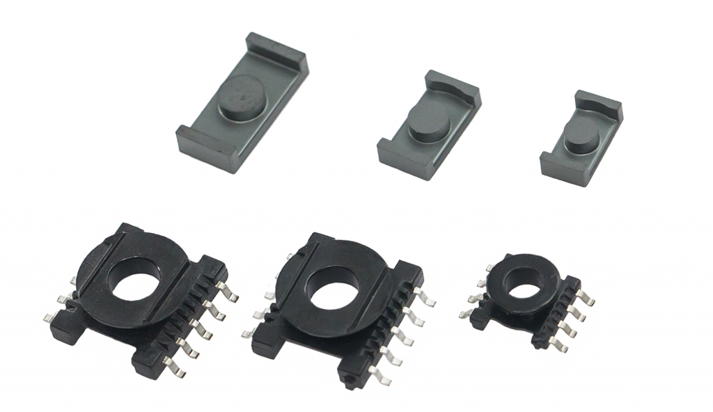

ER, EQ
Integrating ferrite cores into the PCB has become a common technology in the power  supply market. In those low-profile designs ferrite planar cores with low losses and high saturation are widespread. The trends are increasing the power density of the throughput transformer and the current in the output inductor. Ferrite cores are considered a key component for these targets. TDK (EPCOS) has extended the range of planar ferrite cores to meet the new requirements.
Besides the standard ELP core series EPCOS offers now extended series of planar cores with the round center post: EQ 13 to EQ 30 and ER 9.5 to ER 32. This wide range of shapes improves the design capabilities for individual power converter solutions. Customer-specific heights can be supplied as well as different air gap requirements for all series. All TDK (EPCOS) planar cores are available in the well-known EPCOS power materials. For frequencies higher than 400 kHz, N49 is recommended. The material N95 is available for several EQ planar cores and provides stable low power losses across a temperature range from +25°C up to 120°C.
- ER cores are the ideal answer when compact winding structures with low leakage inductance are needed. The round center leg is an advantage together with thick wires or bands.
- Because of their good thermal response, ER cores are especially suitable for applications with high power density. E.g. they are used in flyback converters for TVs and monitors.
ER cores Dimensions

EQ cores Dimensions

Infomation for Ordering
the AL value tolerances for ER cores have consequently been defined with consideration of optimized process parameters for all materials with an initial permability μi in the region of 2200 to 10000.
Example of EPCOS ordering code structure:
ER11/5 — Core shape
B66525 — Part number
000 - ungapped
87 - SIFERRITE material.

