
EMC Countermeasures of Low Voltage Differential Signaling Circuits
Introduction
Low Voltage Differential Signaling (LVDS) is the most common differential transmission system, and it is used for many devices that require high-speed transmission because of its general-purpose properties. As mention is another chapter, USB 2.0 and DVI, HDMI, and DisplayPort are external interfaces that are used to connect devices. However, LVDS is used as an internal interface for many devices for connecting baseplates. This can be used for various purposes and is therefore used by many devices. This section will discuss issues related to EMC which can occur with LVDS, along will solutions using displays as examples such as TVs and monitors. Figure 1 shows some of the LVDS configurations for connecting the main baseplate and panel of a display. Generally, the LVDS circuit consists of clock and data lines, and are configured according to the following. LINK = Clock × 1 + Data × 5Figure 1 LVDS Configuration Example
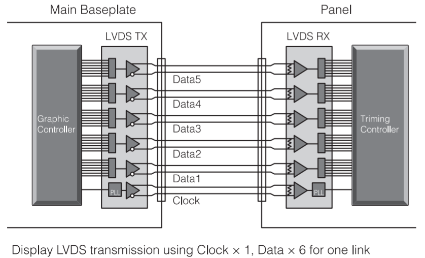
Figure 2 Factors that Contribute to In-Phase Induced Radiation Noise

The transmission rate for one data line is the clock frequency multiplied by seven. For example, when the clock frequency is 74 MHz, Data Line 1 is 518 Mbps, and the basic frequency is 259 MHz. Recently, TVs have come to have higher definition displays, so the transmission capacity of one LINK is not sufficient, so in some cases the number of LINKs has increased to two. In such cases, the configuration is Clock × 1 + Data × 10, nearly doubling the number of lines.
EMC Issues Related to LVDS
With LVDS, termination ends at 100 Ω between differential lines, and impedance matching is executed for the differential signal. However, in-phase components are nearly open, so in-phase components are reflected at the terminal end. The reflected in-phase components are propagated through the cables that connect the baseplates, which can cause unnecessary radiation. Basic noise countermeasures involve removing in-phase components, which is especially important for LVDS because in-phase components have a major effect on it. Therefore, in order to implement noise countermeasures for LVDS, it is important to understand the location and cause of in-phase components. The possible locations of in-phase components are the baseplates and cables that consist of physical layers (Figure 2).
The following are the factors related to the occurrence of in-phase components with baseplates and cables:
a) S+ / S– phase shifting at the output of the LVDS driver
b) Variations of the baseplate material (electric permittivity)
c) Wire unbalanceCables
Cable specifications are not regulated for LVDS as is the case with HDMI, DVI, so various types of cables are used such as FPCs, twin axial cables, and twist pair cables. The waveform quality differs according to the cable because the transmission characteristics are different according to the type.
However, it is believed that factors causing noise radiation are the same (The processing method for connections between the harness and plug connection / GND also effects noise radiation, so it is an important factor to consider for noise countermeasures, but it differs according to the type of cable and the cable manufacturer, so it is not considered here as a general factor.).
The following are the factors related to cable noise radiation:d) Unbalance between the differential pair + and – lines, and weak electromagnetic couple of the + line and – line can cause differential signals to be converted to in-phase components.
e) GND noise on the baseplate is propagated through the sealed coating of the cable, and the cable acts as an antenna, becoming a noise source. If a cable is the main cause of noise radiation, the effectiveness of noise countermeasures implemented to the baseplate is limited, so it is important to select cables carefully.
Effective Usage of Common Mode
Common Mode Filters, which are components used for EMC countermeasures, are effective for suppressing baseplate in-phase noise radiation causes a), b), and c) (Figure 3).
TDK has a wide lineup of Common Mode Filters for meeting various needs. It is important to select components carefully in order to improve the EMC of high-speed differential interfaces.
Common Mode Filters must have the following two characteristics:
1. Not attenuate differential signals
2. Have a high common mode rejection ratioCharacteristic 1 means that the filter does not affect the signal so that signal quality can be ensured, even when loss is proportionally large to the cable length and type for the size of the panel. As for characteristic 2, a higher common rejection ration is needed in order to suppress noise over the 10 MHz band, whichis assumed for low resolution because the LVDS clock signal changes according to the resolution. Common Mode Filter parameters related to the above two characteristics are according to the following.
1 → Differential characteristic impedance (LVDS characteristic impedance is 100 Ω)2 → Common mode impedance
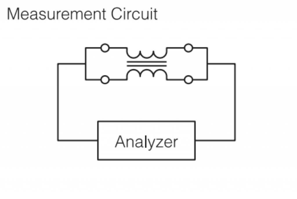
The common mode impedance can be referenced in one of our catalogs (Figure 4).
Figure 4 Common Mode Filter Frequency
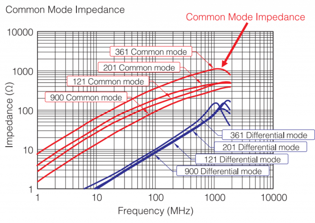
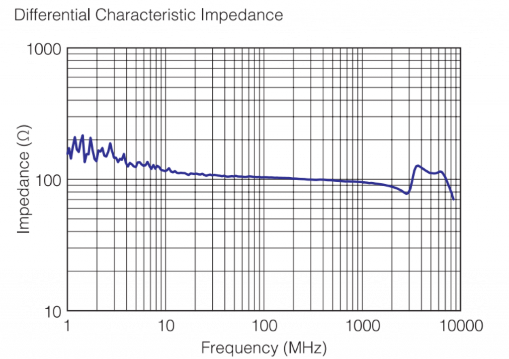
The differential characteristic impedance can not be referenced in one of our catalogs, so please inquire about this to TDK directly. However, all TDK Common Mode Filters have been developed taking into consideration the differential characteristic impedance, so signal quality is good when the recommended component is used. Figure 5 shows a lineup of TDK Common Mode Filters for LVDS. The 2012 size filter is compatible with an impedance of 1000 Ω at 100 MHz. The maximum impedance for 1210 size filter is 400 Ω. The TCM-L Series shown in the figure was specially developed for LVDS, and its characteristics will be explained later.
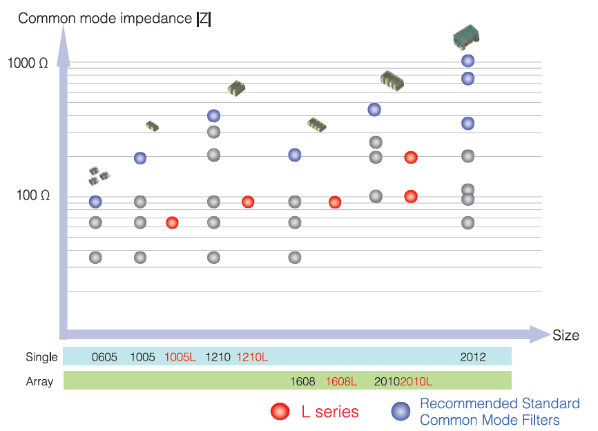
Figure 5 - The higher the common mode impedance, the more effective it is at removing in-phase components. It is recommended to use the filter with the highest impedance for each size. The L Series was specially developed for LVDS. These components are effective for long cables, as is explained later.
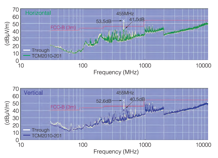
In addition to the electrical characteristics mentioned above, size is also an important factor. LVDS lines consist of 5 to 11 differential lines including clock lines, which require more filters according to the number of lines. Therefore, filters need to be small. TDK’s lineup includes the smallest single component filters in the industry (0605 size), and array components including 1608 size filters, which allow us to meet various demands. Up to here, features of Common Mode Filters and TDK-LVDS Common Mode Filters have been explained. From now, their efficiency will be explained using evaluation results from actual sets. Figure 6 shows the waveform measurement results for a computer. The clock frequency was 65 MHz and the Data rate was 455 Mbps. It was found that the waveform quality was not affected by the Common Mode Filter. Figure 7 shows the results of the noise radiation measurement for the computer. The filter was shown to be effective at the peak frequency of the noise, which was 455 MHz.
Figure 6 The waveform measurement results for a computer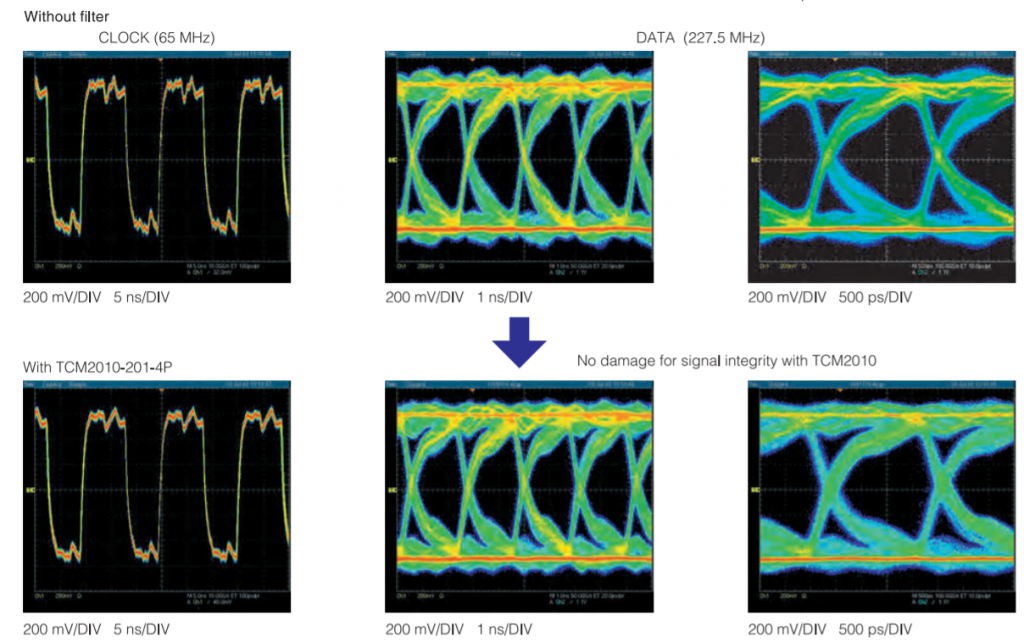
Figure 7 Effectiveness Examples of Common Mode Filters for Suppressing Radiation Noise (Using Filters with a Common Mode Impedance of 200 Ω)
Common Mode Filters for LVDSFeatures and Effectiveness of the TCM-L Series
Common Mode Filters are effective for suppressing LVDS radiation noise, but in recent years, panels have become larger and LVDS cables have become longer, creating new problems. The following two problems exist.
-
Because of the longer cables, impedance mismatching occurs causing waveform quality to deteriorate.
-
Because of the longer cables, the radiation noise level increases.
In such cases, the Common Mode Filters mentioned in the previous section 3 may have only limited effectiveness. To resolve this problem, the TCM-L Series was developed.
These Common Mode Filters are effective for the two problems mentioned above according to the following:
-
→ They remove reflected components so that waveform quality can be improved.
-
→ They reduce the radiation noise level. (By improving differential characteristics → In-phase components are removed.)
Figure 8 shows the measurement results for the LVDS waveform using TCM-L Series filters. When no filter was used, the Eye Diagram showed superimposed high-frequency components on the waveform due to reflection. In this situation, the waveform quality did not change even when TCM2010-201-4P was used. However, when TCM2010L-201-4P was used, the reflected components of the high-frequency wave could be removed, and the eye became wider. As a result, the waveform quality.
Figure 8 Examples of Waveform Shapes when TCM-L Series Filters are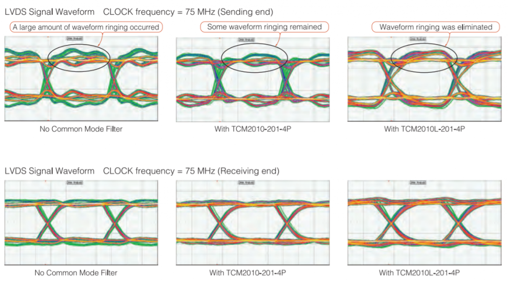
Next, Figure 9 shows the radiation noise measurement results. The CLOCK frequency was set to 135 MHz in order to create strict EMC conditions. The cable was a twin axial cable, which is often used for LVDS. When no filter was used (Figure 9a), a strong peak was found in the harmonics of the LVDS signal. When TCM2010-201-4P was used (Figure 9b), this was removed, but the peak was still obvious at 500 MHz and higher. Therefore, TCM2010L-201-4P was used, and as a result, the peak no longer exists at 810 MHz (Figure 9c).
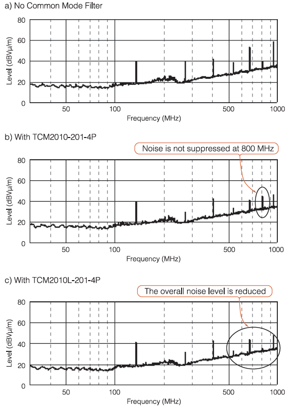
This series of filters is effective for frequencies where normal Common Mode Filters are not effective, which indicates that they are effective for radiation noise related to cables.
TDK Thin-Type Clamp Filters
Figure 9 shows the noise measurement results. It was found that the harmonics components remained at 135 MHz, which is assumed to be clock noise superimposed on the GND line. Clamp filters are effective for suppressing in-phase components such GND system noise for the whole cable. TDK has developed thin-type clamp filters. Figure 10 shows a clamp filter for flat cables.
Figure 10 TDK’s Thin-Type Clamp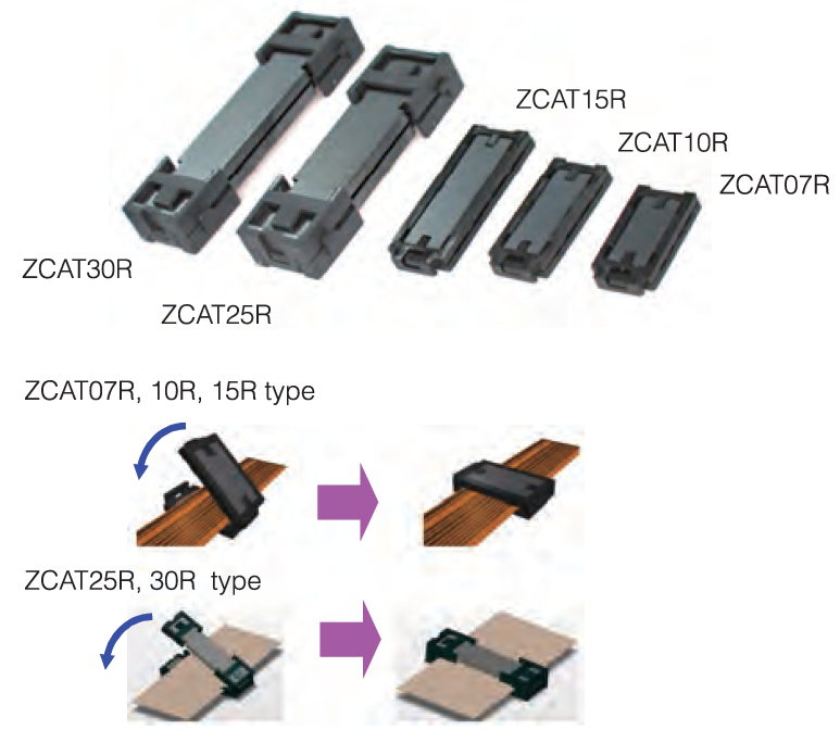
TDK's thin-type clamp filters, which have the same ferrite core. These filters are good for devices which limited space such as LCD-TVs, PDP-TVs, DSCs, and DVCs.
Conclusion
The features and effectiveness of Common Mode Filters for LVDS was explained here. It can be said that Common Mode Filters are effective for reducing in-phase noise generated by baseplates. The TCM-L Series can also be used to effectively resolve radiation noise problems related to cables. Therefore, these components can be used as noise countermeasures. In the future, display resolutions will continue to increase, so it is expected that new interfaces (DisplayPort and V-by-One) will become replacements. However, because LVDS is an established and low-cost technology, it will continue to play a major role as an interface between baseplates. Therefore, LVDS noise countermeasures will continue to be important. It is also believed that the need for the components introduced here will increase as wireless devices become equipped on TVs. TDK has been making efforts to provide solutions to the latest problems related to EMC. Please do not hesitate to consult with TDK.

